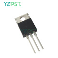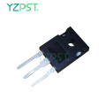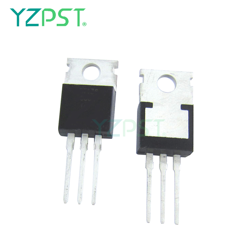
TO-220 scr位相制御25Aトランジスタ25TTS12
$0.252000-99999 Piece/Pieces
$0.22≥100000Piece/Pieces
| お支払い方法の種類: | L/C,T/T,Paypal |
| インコタームズ: | FOB,CFR,CIF |
| 最小注文数: | 2000 Piece/Pieces |
| 輸送方法: | Ocean,Air |
| ポート: | SHANGHAI |

$0.252000-99999 Piece/Pieces
$0.22≥100000Piece/Pieces
| お支払い方法の種類: | L/C,T/T,Paypal |
| インコタームズ: | FOB,CFR,CIF |
| 最小注文数: | 2000 Piece/Pieces |
| 輸送方法: | Ocean,Air |
| ポート: | SHANGHAI |
モデル: YZPST-25TTS12
ブランド: YZPST
| 販売単位 | : | Piece/Pieces |
| パッケージ型式 | : | 1.帯電防止包装2.カートン箱3.プラスチック保護包装 |
位相制御SCR、25 A
説明/機能
25TTS ...高電圧シリーズのシリコン制御整流器は、中電力スイッチングおよび位相制御アプリケーション用に特別に設計されています。使用されるガラスパッシベーション技術は、信頼性の高い動作を
接合部温度は125°Cです。
代表的なアプリケーションは入力整流(ソフトスタート)であり、これらの製品は同一パッケージ外形で入手可能なVishay HPP入力ダイオード、スイッチおよび出力整流器と共に使用するように設計されています。
この製品は工業レベル用に設計され認定されています。

|
PRODUCT SUMMARY |
|
|
VT at 16 A |
< 1.25 V |
|
ITSM |
300 A |
|
VRRM |
800/1200 V |
|
OUTPUT CURRENT IN TYPICAL APPLICATIONS |
|||
|
APPLICATIONS |
SINGLE-PHASE BRIDGE |
THREE-PHASE BRIDGE |
UNITS |
|
Capacitive input filter TA = 55 °C, TJ = 125 °C, common heatsink of 1 °C/W |
18 |
22 |
A |
|
MAJOR RATINGS AND CHARACTERISTICS |
|||
|
PARAMETER |
TEST CONDITIONS |
VALUES |
UNITS |
|
IT(AV) |
Sinusoidal waveform |
16 |
A |
|
IRMS |
|
25 |
|
|
VRRM/VDRM |
|
800/1200 |
V |
|
ITSM |
|
300 |
A |
|
VT |
16 A, TJ = 25 °C |
1.25 |
V |
|
dV/dt |
|
500 |
V/µs |
|
dI/dt |
|
150 |
A/µs |
|
TJ |
|
- 40 to 125 |
°C |
|
VOLTAGE RATINGS |
|||
|
PART NUMBER |
VRRM, MAXIMUM PEAK REVERSE VOLTAGE V |
VDRM, MAXIMUM PEAK DIRECT VOLTAGE V |
IRRM/IDRM AT 125 °C mA |
|
25TTS08 |
800 |
800 |
10 |
|
25TTS12 |
1200 |
1200 |
|
|
ABSOLUTE MAXIMUM RATINGS |
||||||
|
PARAMETER |
SYMBOL |
TEST CONDITIONS |
VALUES |
UNITS |
||
|
TYP. |
MAX. |
|||||
|
Maximum average on-state current |
IT(AV) |
TC = 93 °C, 180° conduction half sine wave |
16 |
A |
||
|
Maximum RMS on-state current |
IRMS |
|
25 |
|||
|
Maximum peak, one-cycle, non-repetitive surge current |
ITSM |
10 ms sine pulse, rated VRRM applied |
300 |
|||
|
10 ms sine pulse, no voltage reapplied |
350 |
|||||
|
Maximum I2t for fusing |
I2t |
10 ms sine pulse, rated VRRM applied |
450 |
A2s |
||
|
10 ms sine pulse, no voltage reapplied |
630 |
|||||
|
Maximum I2√t for fusing |
I2√t |
t = 0.1 to 10 ms, no voltage reapplied |
6300 |
A2√s |
||
|
Maximum on-state voltage drop |
VTM |
16 A, TJ = 25 °C |
1.25 |
V |
||
|
On-state slope resistance |
rt |
TJ = 125 °C |
12.0 |
mΩ |
||
|
Threshold voltage |
VT(TO) |
1.0 |
V |
|||
|
Maximum reverse and direct leakage current |
IRM/IDM |
TJ = 25 °C |
VR = Rated VRRM/VDRM |
0.5 |
mA |
|
|
TJ = 125 °C |
10 |
|||||
|
Holding current |
IH |
Anode supply = 6 V, resistive load, initial IT = 1 A |
- |
100 |
||
|
Maximum latching current |
IL |
Anode supply = 6 V, resistive load |
200 |
|||
|
Maximum rate of rise of off-state voltage |
dV/dt |
|
500 |
V/µs |
||
|
Maximum rate of rise of turned-on current |
dI/dt |
|
150 |
A/µs |
||
|
TRIGGERING |
||||
|
PARAMETER |
SYMBOL |
TEST CONDITIONS |
VALUES |
UNITS |
|
Maximum peak gate power |
PGM |
|
8.0 |
W |
|
Maximum average gate power |
PG(AV) |
|
2.0 |
|
|
Maximum peak positive gate current |
+ IGM |
|
1.5 |
A |
|
Maximum peak negative gate voltage |
- VGM |
|
10 |
V |
|
Maximum required DC gate current to trigger |
IGT |
Anode supply = 6 V, resistive load, TJ = - 10 °C |
60 |
mA |
|
Anode supply = 6 V, resistive load, TJ = 25 °C |
45 |
|||
|
Anode supply = 6 V, resistive load, TJ = 125 °C |
20 |
|||
|
Maximum required DC gate voltage to trigger |
VGT |
Anode supply = 6 V, resistive load, TJ = - 10 °C |
2.5 |
V |
|
Anode supply = 6 V, resistive load, TJ = 25 °C |
2.0 |
|||
|
Anode supply = 6 V, resistive load, TJ = 125 °C |
1.0 |
|||
|
Maximum DC gate voltage not to trigger |
VGD |
TJ = 125 °C, VDRM = Rated value |
0.25 |
|
|
Maximum DC gate current not to trigger |
IGD |
2.0 |
mA |
|
|
SWITCHING |
||||
|
PARAMETER |
SYMBOL |
TEST CONDITIONS |
VALUES |
UNITS |
|
Typical turn-on time |
tgt |
TJ = 25 °C |
0.9 |
µs |
|
Typical reverse recovery time |
trr |
TJ = 125 °C |
4 |
|
|
Typical turn-off time |
tq |
110 |
||
|
THERMAL AND MECHANICAL SPECIFICATIONS |
|||||
|
PARAMETER |
SYMBOL |
TEST CONDITIONS |
VALUES |
UNITS |
|
|
Maximum junction and storage temperature range |
TJ, TStg |
|
- 40 to 125 |
°C |
|
|
Maximum thermal resistance, junction to case |
RthJC |
DC operation |
1.1 |
°C/W |
|
|
Maximum thermal resistance, junction to ambient |
RthJA |
|
62 |
||
|
Typical thermal resistance, case to heatsink |
RthCS |
Mounting surface, smooth and greased |
0.5 |
||
|
Approximate weight |
|
|
2 |
g |
|
|
0.07 |
oz. |
||||
|
Mounting torque |
minimum |
|
|
6 (5) |
kgf · cm (lbf · in) |
|
maximum |
|
|
12 (10) |
||
|
Marking device |
|
Case style TO-220AB |
25TTS08 |
||
|
25TTS12 |
|||||


電話番号: 86-514-87782298
Whatsapp: +8613805278321
住所: 3rd Floor, Weiheng Building No.20 B Area, Yangzhou, Jiangsu China
ウェブサイト: https://jp.yzpst.com


Privacy statement: Your privacy is very important to Us. Our company promises not to disclose your personal information to any external company with out your explicit permission.
Fill in more information so that we can get in touch with you faster
Privacy statement: Your privacy is very important to Us. Our company promises not to disclose your personal information to any external company with out your explicit permission.